Blind
2.3L
CAFords OG
Member # 3052
|
 posted


Checking codes is perhaps the most important step in diagnosing problems with your 5.0. It is free, easy, and effective.
Materials Needed
-a paperclip or a piece of wire approximately 3-10 inches
-pen and paper
To get accurate results it is important that the car is fully warmed up
Step One
-Find the self-test connectors. They are located behind the driver side strut tower if your Mustang is a 1986-1993, and behind the passenger side strut tower if your Mustang is a '94-'95.
1986 - 1993 Mustangs VIP Connector Location


1994 - 1995 Mustangs VIP Connector Location
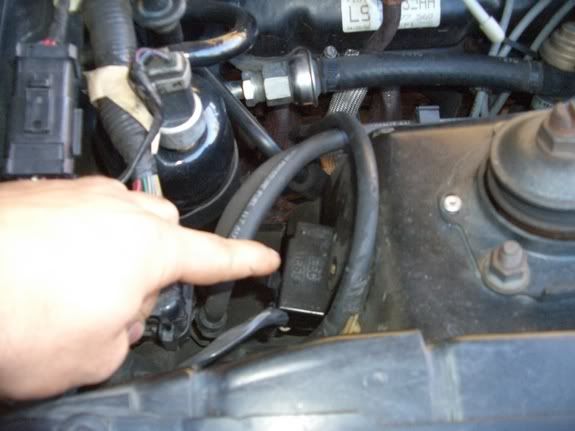
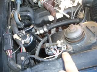
-Connect the Self-Test Input (the single wire connector) to the SigRTN (the top right "window" of the house-shaped connector) using the paperclip or the wire.

Step Two
-Now that the connection is made, grab your pen and paper and sit in the driver seat.
-Turn the key to the on position, but do not start the car. This will initiate the "Key On Engine Off" or KOEO Test.
-Keeping an eye on the Check Engine Light (CEL) you will notice a quick and brief series of flashes. These are not usuable for these tests.
-Next the CEL will flash slower codes. These codes are the ones we want, so its time to start counting them. The spacing of the flashes determines the number, for example: a code 67 would be shown as 6 flashes in a row, then a small pause, followed by 7 more flashes. Between codes is a longer pause. Each code will be repeated twice.
-When the KOEO codes stop, you'll notice a much longer pause and then a seperator pulse (a single "solid" flash).
-Now the Continuous Memory (CM) codes will flash. These codes are output essentially the same way as the KOEO codes.
Step Three
-after the CM codes are finished, turn the key to off for about 10 seconds, but leave the Self-Test connection hooked up.
-Now you will want to start the car. The idle will raise substantially and the CEL will flash four times in a row (indicating that you have eight cylinders)
-this will be followed by the Key On Engine Running (KOER) codes that are output like the previous tests.
Step Four
- If failure codes were retrieved from any of the self-tests, register at my5oh.com, access our Codes Description and Codes Troubleshooting Database, and lets fix your Mustang ....we'll help you with any question or interpretation of the results......
- Start by Checking your codes here:
http://www.my5oh.com/forum/viewtopic.php?t=197
Optional Testing
Cylinder Balance Test
-Immediately after all KOER codes have been output, a quick WOT rev will initiate the cylinder balance test.
-The codes shown are of a slightly different format, that is, they are multiples of ten. 10, 20, 30, 40, etc. for example 9 flashes would equal 90.
EEC-IV Self-Test Codes
OKey On, Engine Off code.
CMContinuous Memory code.
REngine Running code.
2-Digit Codes
11 - System Pass (O,CM,R)
12 - RPM Not Within Self Test Lower Limit (R), DC Motor Did Not Move (O,CM,R), Idle Speed Control motor or Air Bypass not controlling idle properly -generally idle too low
13 - RPM Not Within Self Test Upper Limit (R), Idle Speed Control motor or Air Bypass not controlling idle properly -generally idle too high
14 - Profile Ignition Pickup Circuit Failure (CM)
15 - Readout Memory Test Failed (O), Keep Alive Memory Test Failed (CM)
16 - RPM Too Low To Perform o2 Sensor Test (R)
17 - RPM below Self-Test limit with Idle Air Control off (R)
18 - Spark Out (SPOUT) Circuit Open (R), Loss Of Ignition Diagnostic Module Input To PCM/SPOUT Circuit Grounded (CM)
19 - Failure In PCM Internal Voltage (R), Erratic RPM During Hard Idle Self Test (R), Failure in EEC reference voltage (O)
21 - Engine Coolant Temperature (ECT) Sensor Out Of Self Test Range. 0.3 to 3.7 volts(O,R)
22 - Manifold Absolute Pressure/Barometric Pressure Sensor Out Of Self Test Range (O,CM,R)
23 - Throttle Position Sensor Out Of Self Test Range (O,CM,R)
24 - Intake Air Temperature/Air Charge Temperature Sensor Out Of Self Test Range. 0.3 to 3.7 volts(O,R)
25 - Knock Not Sensed During Dynamic Response Test (R)
26 - Mass Air Flow Sensor was greater than 0.7 volts with engine off (O), MAF sensor was not between 0.2 and 1.5 volts with engine running (R).
28 - Loss Of Ignition Diagnostic Module RH Side (CM)
29 - Insufficient Input From Vehicle Speed Sensor -To 1992 (CM), Insufficient Input From Programmable Speedometer/Odometer Module -From 1993 (CM)
31 - EGR Valve Position/Pressure Feedback EGR Circuit Below Minimum Voltage. 0.24 volts (O,CM,R)
32 - EGR Valve Position/Pressure Feedback EGR Voltage Below Closed Voltage. 0.24 volts (O,CM,R)
33 - EGR Valve Opening Not Detected (CM,R)
34 - EGR Valve Position/Pressure Feedback EGR Voltage Above Closed Limit (O,R), PFE or EVP circuit has intermittently failed above the closed limit of 0.67 volts (CM)
35 - EGR Valve Position/EGR Pressure Feedback EGR Circuit Above Maximum Voltage of 4.81 volts (O,R), PFE or EVP circuit has intermittently failed above the maximum limit of 4.81 volts (CM)
36 - System Indicates Lean At Idle (R)
37 - System Indicates Rich At Idle (R)
39 - AXOD converter bypass clutch not applying properly (CM)
41 - System Indicates Lean -passenger side(R), No o2 Sensor Switching Detected. always lean -passenger side(CM)
42 - System Indicates Rich -passenger side(R), No o2 Sensor Switching Detected. always rich -passenger side(CM)
43 - o2 Sensors indicate lean at Full Throttle (CM)
44 - Secondary Air System Inoperative. bank one, passenger side (R)
45 - Secondary Air Upstream During Self Test (R)
46 - Secondary Air Not Bypassed During Self Test (R)
47 - Measured Air Flow Low At Base Idle (R)
48 - Measured air flow too high at base idle (R)
49 - 12 Shift Error (CM)
51 - Engine Coolant Temperature Circuit Open (CM,O)
52 - Power Steering Pressure Switch Circuit Open (O), Power Steering Pressure Switch Circuit Did Not Change States (R)
53 - Throttle Position Sensor Circuit Above Maximum Voltage (CM,O)
54 - Intake Air Temperature/Air Charge Temperature Circuit Open (CM,O,R)
55 - Key Power Check (R)
56 - Mass Air Flow/Vane Air Flow Sensor Circuit Above Maximum Voltage (O,CM,R), MAF Sensor short to power (CM,R), Transmission Fluid Temperature Circuit Open (CM,O)
57 - AXOD Neutral pressure switch circuit failed open (CM)
58 - Idle Tracking Switch Circuit Open Or Grounded -CFI (O,R), Vane Air Temperature Sensor Input Greater Than Self Test Maximum -EFI (CM,O)
59 - 23 Shift Error (CM), AXOD 4/3 Pressure Switch Circuit Failed Closed (O), AXOD 4/3 Pressure Switch Circuit Failed Open (C)
61 - ECT Sensor Circuit Grounded (O,CM,R)
62 - Torque Converter Clutch Error (C,M), AXOD 4/3 Or 3/2 Pressure Switch Circuit Grounded (O)
63 - Throttle Position Sensor Circuit Below Minimum Voltage (O,CM,R)
64 - Intake Air Temperature/Air Charge Temperature Circuit Grounded (O,CM,R)
65 - Transmission Control Switch/Overdrive Cancel Switch Circuit Did Not Change States (R)
66 - , MAF signal below minimum test voltage of .4vdc (O,CM,R), Transmission Fluid Temperature Circuit Grounded (CM,O)
67 - Park Neutral Position Switch Circuit Open; A/C On -Manual (O), Manual Lever Position Sensor Out Of Range/A/C On (CM,O), Clutch Switch Circuit Failure (CM)
68 - Transmission recently overheated, or TOT sensor intermittently failed below 0.2 volts (CM)
69 - 34 Shift Error (CM)
71 - Software re-initialization detected or Cluster Control Assembly circuit failed (CM)
72 - Insufficient Manifold Absolute Pressure/Mass Air Flow Change During Dynamic Response Test (R)
73 - Insufficient Throttle Position Change During Dynamic Response Test (O,R)
74 - Brake On/Off Circuit OpenNot During Self Test (CM,R)
75 - Brake On/Off Circuit Closed/ECA Input Open (R)
76 - Insufficient Vane Air Flow Sensor Output Change During Dynamic Response Test (R)
77 - Operator Error Dynamic Response Test (R)
78 - Re-Initalization Check (R)
79 - A/C On/Defrost On During Self Test (O)
81 - Secondary Air Diverter Circuit Failure (O)
82 - Secondary Air Bypass Circuit Failure (O)
83 - EGR Control solenoid circuit failure (O)
84 - EGR Vacuum Regulator (EVR) Control Circuit Failure (O)
85 - CANP Circuit Failure (O)
86 - Adaptive fuel limit reached (CM), 3 4 Shift solenoid circuit failure (O)
87 - Primary Fuel Pump Circuit Failure (CM,O)
88 - Loss Of Dual Plug Input Control (CM), Throttle Kicker Fault (?)
89 - Converter clutch solenoid circuit failure (CM)
91 - o2 Sensor Circuit Indicates Lean -driver side(R), No o2 Sensor Switching Detected. always lean -driver side(CM), Shift Solenoid 1 Circuit Failure (O)
92 - o2 Sensor Circuit Indicates Rich -driver side(R), No o2 Sensor Switching Detected. always rich -driver side(CM), Shift Solenoid 2 Circuit Failure (O)
93 - Converter Clutch Solenoid Circuit Failure (O)
94 - Secondary Air Injection Inoperative. bank two, driver side (R), Torque Converter Clutch Solenoid Circuit Failure (O)
95 - Fuel Pump Circuit Open-PCM To Motor Ground (CM,O)
96 - Fuel Pump Circuit Open-Battery To PCM (CM,O)
97 - Transmission Control Indicator Lamp Circuit Failure (O)
98 - Hard Fault Present (R)
99 - Electronic Pressure Control Circuit Failure (CM,O)
Cylinder Balance Test Codes
10 - Cylinder #1 Failed Cylinder Balance Test
20 - Cylinder #2 Failed Cylinder Balance Test
30 - Cylinder #3 Failed Cylinder Balance Test
40 - Cylinder #4 Failed Cylinder Balance Test
50 - Cylinder #5 Failed Cylinder Balance Test
60 - Cylinder #6 Failed Cylinder Balance Test
70 - Cylinder #7 Failed Cylinder Balance Test
80 - Cylinder #8 Failed Cylinder Balance Test
90 - All cylinders passed Cylinder Balance Test
3-Digit Codes
OKey On, Engine Off code.
CMContinuous Memory code.
REngine Running code.
111 - System Pass
112 - ACT Sensor Circuit Below Minimum Voltage of 0.2 volts (O), ACT circuit has intermittently failed below minimum 0.2 volts (CM)
113 - ACT Sensor Circuit Above Maximum Voltage of 4.6 volts (O), ACT circuit has intermittently failed above the maximum of 4.6 volts (CM)
114 - ACT out of self test range 0.3 to 3.7 volts
116 - ECT out of self test range 0.3 to 3.7 volts
117 - ECT Sensor Circuit Below Minimum Voltage of 0.2 volts(O), ECT circuit has intermittently failed below minimum 0.2 volts (CM)
118 - ECT Sensor Circuit Above Maximum Voltage of 4.6 volts (O), ECT sensor circuit has intermittently failed above the maximum of 4.6 volts (CM)
121 - Closed throttle TPS voltage higher or lower than expected (O,R), TP sensor was inconsistent with the MAF/MAP value in the last 80 drive cycles (CM)
122 - TPS circuit below minimum 0.6 volts (O), TPS circuit has intermittently failed below minimum 0.6 volts (CM)
123 - TP circuit above maximum 4.5 volts (O), TPS circuit has intermittently failed above maximum 4.5 volts (CM)
124 - TP sensor was higher than expected with the MAF/MAP value in the last 80 drive cycles (CM)
125 - TP sensor was lower than expected with the MAF/MAP value in the last 80 drive cycles (CM)
126 - MAP/BP sensor out of self test range 1.4 to 1.6 volts
128 - MAP sensor vacuum was not greater than 2 in-Hg (7 kPa) during normal vehicle operation
129 - Insufficient MAF/MAP change during Dynamic Response Test
136 - o2 Sensor circuit indicates system lean (left side)
137 - o2 Sensor circuit indicates system rich (left side)
139 - No HEGO sensor switching detected or disconnected (left side)
141 - o2 Sensor circuit indicates system lean (both sides)
144 - No o2 Sensor switching detected or disconnected (right side)
157 - MAF sensor went below 0.4 volts during the last 80 warm-up cycles
158 - MAF sensor went above 4.5 volts during the last 80 warm-up cycles
159 - MAF signal was greater than 0.70 volt during KOEO (O), MAF signal was not between 0.20 and 1.50 volts during KOER (R)
167 - TPS did not exceed 25% rotation during the Dynamic Response Test
171 - Fuel system at adaptive limit, o2 Sensor unable to switch (right side)
172 - o2 Sensor sensor circuit indicates system lean (right side)
173 - o2 Sensor sensor circuit indicates system rich (right side)
174 - o2 Sensor switching time is slow
175 - Fuel system at adaptive limit, o2 Sensor unable to switch(left side, (Bank No. 2))
176 - o2 Sensor circuit indicates system lean (left side)
177 - o2 Sensor circuit indicates system rich (left side)
178 - o2 Sensor switching time is slow (Bank No. 1)
179 - Right side still rich, at leanest adaptive limit, during part throttle
181 - Right side still lean, at richest adaptive limit, during part throttle
182 - Right side still rich, at leanest adaptive limit, at idle
183 - Right side still lean, at richest adaptive limit, at idle
184 - MAF higher than expected
185 - MAF lower than expected
186 - Injector pulse width longer than expected
187 - Injector pulse width shorter than expected
188 - Left side still rich, at leanest adaptive limit, during part throttle
189 - Left side still lean, at richest adaptive limit, during part throttle
191 - Left side still rich, at leanest adaptive limit, at idle
192 - Left side still lean, at richest adaptive limit, at idle
193 - Flexible Fuel sensor circuit failure
194 - Run cylinder balance diagnostic test
195 - Run cylinder balance diagnostic test
211 - Two or more successive erratic Profile Ignition Pickup (PIP) pulses occurred, resulting in a possible engine miss or stall
212 - Loss of IDM (Ignition Diagnostic Monitor) input to EEC or SPOUT circuit grounded
213 - SPOUT circuit open
214 - Cylinder Identification (CID) circuit failure
215 - EEC detected coil 1 primary circuit failure
216 - EEC detected coil 2 primary circuit failure
217 - EEC detected coil 3 primary circuit failure
218 - Loss of IDM (Ignition Diagnostic Monitor) signal (left side)
219 - SPOUT failure, spark timing has defaulted to 10 degrees BTDC
222 - Loss of IDM (Ignition Diagnostic Monitor)signal (right side)
223 - Loss of Dual Plug Inhibit control
224 - Erratic IDM (Ignition Diagnostic Monitor)input to processor
225 - Knock Sensor (KS) signal not sensed during dynamic response test
226 - IDM (Ignition Diagnostic Monitor)signal not received
244 - Camshaft Position (CMP) Sensor failure
311 - Thermactor air system inoperative (right side)
312 - Thermactor air misdirected upstream during self test
313 - Thermactor air not bypassed during self test
314 - Thermactor air system inoperative (left side)
326 - PFE or DPFE circuit voltage lower than expected with zero EVR duty cycle
327 - DPFE or EVP circuit below minimum voltage of 0.2 volts
328 - EVP circuit below minimum voltage of 0.24 volts
332 - EGR valve opening not detected
334 - DPFE or EVP circuit above the closed limit of 0.67 volts
335 - PFE or DPFE sensor voltage out of Self-Test range
336 - EVP or DPFE circuit voltage above maximum voltage with zero EVR duty cycle
337 - DPFE or EVP circuit above the maximum limit of 4.81 volts
338 - ECT lower than expected
339 - ECT higher than expected
341 - Octane Adjust shorting bar is not in or the OCT ADJ circuit is open
381 - Frequent A/C compressor clutch (ACCS) cycling less than 8.5 seconds
411 - Cannot control rpm during KOER low RPM check
412 - Cannot control rpm during KOER high RPM check
452 - Computer detected an error in the VSS or PSOM signal during the last 80 warm-up cycles
461 - Engine over speed was detected
511 - EEC permanent Read Only Memory (ROM) test failed
512 - EEC battery powered Keep Alive Memory (KAM) test failed
513 - Failure in EEC processor internal voltage
519 - Power steering pressure switch circuit open
521 - Power steering pressure switch did not change state during KOER test
522 - Vehicle not in PARK or NEUTRAL during KOEO
524 - When the PCM commanded the fuel pump on, voltage was not detected on FPM
525 - Vehicle in gear or A/C on during Self-Test
526 - Neutral Pressure Switch closed or A/C on
527 - Neutral Drive Switch open or A/C on
528 - Clutch Switch Circuit failure
529 - Data Communications Link or Electronic Instrument Cluster circuit failure
532 - Data Communications Link or Electronic Instrument Cluster circuit failure
533 - Data Communications Link or Electronic Instrument Cluster circuit failure
536 - Brake On/Off circuit failure / switch not actuated during KOER test
538 - Insufficient RPM change during KOER dynamic response test/ Operator error
539 - A/C or Defroster ON during KOEO test
542 - Fuel pump circuit failure
543 - When the PCM commanded the fuel pump on, voltage was not detected on FPM
551 - Intake Manifold Runner Control (IMRC) circuit failure
552 - Air management 1 circuit failure (AM1/TAB)
553 - Air management 2 circuit failure (AM1/TAD)
554 - Fuel Pressure Regulator Control (FPRC) solenoid circuit failure
556 - Fuel Pump circuit failure
557 - Fuel pump relay coil resistance failure
558 - EGR Vacuum Regulator circuit failure
559 - Air Conditioning On relay circuit failure
563 - High Speed Electro-Drive Fan circuit failure
564 - Electro-Drive Fan circuit failure
565 - Canister purge circuit failure
566 - 3 4 Shift Solenoid failure
569 - Canister purge 2 circuit failure
571 - EGR Atmospheric Regulator circuit failure
572 - EGR Vacuum Regulator circuit failure
578 - A/C Pressure (ACP) sensor VREF circuit is short to ground
579 - A/C Pressure (ACP) sensor circuit is above maximum voltage
581 - When the cooling fan was activated, the circuit exceeded current draw
582 - Open or short to power in the power-to-cooling fan circuit
583 - When the fuel pump was activated, the power-to-pump circuit exceeded the normal current draw
584 - Variable Control Relay Module circuit grounded
585 - A/C clutch circuit exceeded the normal current draw
586 - A/C clutch circuit open or shorted to power
587 - Data Communications Link (DCL) error
593 - Oxygen Sensor Heater circuit failure
617 - 1 - 2 shift error (E4OD)
618 - 2 - 3 shift error (E4OD)
619 - 3 - 4 shift error (E4OD)
621 - Shift solenoid #1 circuit failure
622 - Shift solenoid #2 circuit failure
623 - Overdrive light circuit failure
624 - Electronic Pressure Control solenoid or driver circuit failure
625 - Electronic Pressure Control driver open in EEC
626 - Coast clutch solenoid circuit failure (E4OD)
627 - Converter clutch solenoid circuit failure (E4OD)
628 - Converter clutch Lock-Up error (E4OD)
629 - Converter clutch control circuit failure
631 - Overdrive light circuit failure
632 - Overdrive cancel switch not changing state (E4OD)
633 - 4WD switch is closed
634 - Transmission Manual Lever Position Sensor circuit out of self test
636 - TOT sensor voltage out of self test range
637 - TOT sensor circuit above maximum voltage
638 - TOT sensor circuit below minimum voltage
639 - Insufficient input from the Transmission Speed Sensor
641 - Shift solenoid #3 circuit failure
643 - Converter Clutch Control circuit failure
645 - Incorrect gear ratio obtained for first gear
646 - Incorrect gear ratio obtained for second gear
647 - Incorrect gear ratio obtained for third gear
648 - Incorrect gear ratio obtained for fourth gear
649 - Electronic Pressure Control range failure
651 - Electronic Pressure Control circuit failure
652 - Modulated Converter Clutch Control solenoid output circuit error
653 - Transmission Control Switch was not cycled during KOER Self-Test
654 - MLP sensor not in park position
656 - Converter Clutch Control continuous slip error detected
657 - Transmission over temperature condition occurred
659 - High vehicle speed detected while the vehicle was in PARK
667 - Transmission Manual Lever Position Sensor circuit shorted
668 - Transmission Manual Lever Position Sensor circuit open
675 - MLP circuit voltage was out of the expected range
691 - 4WD switch circuit failure
998 - Hard fault present
--------------------
89 LX Notchback ex 4cyl, 14psi
02 Harley F150, 15psi
Posts: 8521 | From: Fairfield | Registered: Jul 2003
| :
|


 Email this post to someone!
 Printer friendly view of this Ford topic

![[Embarrassed]](redface.gif)
![[patriot]](graemlins/patriot.gif) , not no "got sidewayz in the intersection and posi aint workin" type of ish!
, not no "got sidewayz in the intersection and posi aint workin" type of ish!


